Several Newell owners I have spoken with have expressed interest in gaining access to the series 60 on a rear bath floorplan. I would guess that my experience may have similarities with rear closet models also. I was at Newell to have the valves adjusted, jake brake adjusted and injector height checked. I'll describe the process and provide photos.
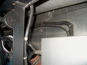
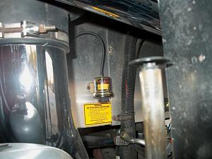
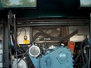
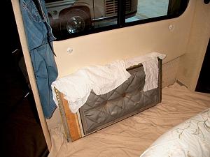
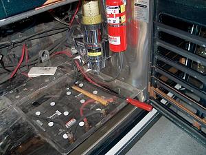
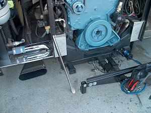
Disassembly began inside the coach with the removal of a mirrored & carpeted board that is on the back wall of the rear closet down by the floor. It is velcroed to the rear wall of the closet. Removing it exposes a access cover to the engine compartment. Next go outside and remove the chrome air tube that runs left to right. Now remove a center section of the aluminum engine firewall. There are five phillips headed screws around the edges that are removed. There are also two 1/4" x 4" bolts on each side of the center section that hold the access door in place. Once the bolts & screws are removed, move the center section over to the right and set on top of the hydraulic reservoir. See photos #1,2 & 3.
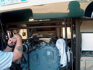
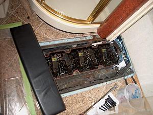
Next remove four 1/4" x 4" bolt that go upward through a 1 1/2" x 1 1/2" frame member into the floor access panel-see photo #4(only one bolt hole visible). There are 2 bolts on each side of the engine that are 20" apart. Both bolts on the right side are easily accessible through the engine access compartment. The left side is more challenging. Remove the coolant tank out of the way. Remove the closest bolt. Now get the skinny guy with the long arms to shimmy in between the left side of the engine and fan and remove the other bolt on the left side. Now push the access door into the coach that was behind the engine firewall center section-see photo #5. In photo #5 you can see the outline of the metal pan that surrounds the floor access cover that needs to be removed. The tech layed on the floor and using a boxcutter, cut out the grout on the outside of the metal pan. This was tedious and took awhile to cut through the grout holding the floor access panel in. Tech said as you worked on cutting the grout you could feel when you were through it. Got to remove as much grout in the thin line as possible to allow floor access panel to come out.
Now the uncomfortable part begins--prying up the floor access panel without breaking the granite floor. They pried from the rear using 1/2" blocks of plywood on the valve cover and from the right side. Prying from the rear was the most effective. As one tech pried the other tech continued to scrape out the grout around the metal pan. This process was slow, tedious, but successful as the floor access panel finally came loose--see photos #6, 7, 8 & 9. We are now 4 hours into the job. There is now access and no chipped or broken granite. Tech said it was the hardest he ever had to pry.
Photo # 10 is looking down at the open engine with the jakes still in place from inside the coach. Adjusting the valves, adjusting the jakes & cheking injector height took about 4 hours. Photo #11 is a polished up valve cover ready for installation--not included in the valve adjustment. Photo # 12 is the valve cover back on the engine and ready to assemble the coach back together in the reverse order of disassembly. The caulking in photo #13 was used in place of grout, looked great and should make removal of the floor access easier next time. Reassembly took another 3 hours. Total time for job was 11 hours.
Couldn't tell any difference in engine performance yet, but the jake brake now works much better. Before I didn't feel the jake working in the low position, now I do.
For those that do not know Detroit Diesel recommends adjusting the valves and jake the first time at 60,000 miles.
I will add the last three photos in a continuing post as I was only allowed to download ten photos. Sorry for the photo issue. The first 10 photos are now in the correct order.
I hope my experience will help others.......................


 Threaded Mode

